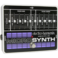
Electro-Harmonix Micro Synthesizer
- Brand: Electro-Harmonix
- Product Code: Electro-Harmonix Micro Synthesizer
- Availability: 1
-
$324.80
Electro-Harmonix Micro Synthesizer
From the classic vintage sounds of the great early Moog synthesizer to custom creations, the Microsynth creates fat analog synth sounds heard on classic recordings by some of the finest musicians in the world. Compact ten-slider layout lets the sonically adventurous guitarist dial in a virtually limitless array of analog synthesizer sounds: from percussive stabs to backwards-sounding bowed effects.
The Micro Synth can create some of the most popular synthesizer textures at a fraction of the cost for such capabilities. Its four voices: GUITAR, OCTAVE, SUB OCTAVE AND SQUARE WAVE are completely independent and fully mixable. The MICRO SYNTH can modify these signals with envelope control for a variety of “bowed” or “blown” sounds. In addition, a sophisticated swept filter control allows highly variable frequency adjustments to be applied to the overall output signal. When combined, these controls offer the user a creative capability that is virtually limitless.
PREAMP GAIN ADJUSTMENT: The preamp gain in the Micro Synth has been set at the factory for use with a guitar equipped with single-coil pickups. If you will be using another instrument with higher or lower output, it may be necessary to readjust this setting. A screwdriver or alignment tool with a tip width of no more than 1/16” is required. To access the preamp gain adjustment, remove the bottom plate from the Micro Synth. Look for the small trim pot in the lower left corner of the circuit board, it is labeled TRIM1 GAIN TRIM. Turning the trim pot clockwise will increase the preamp gain. Turning it counter-clockwise will decrease preamp gain. Please do not touch any other components when the bottom plate is removed or you risk damaging the circuit board or the components.
OPERATION: The Micro Synth’s controls operate as described below. In all cases, high-numbered control settings increase the level of the given effect.
FOOTSWITCH and Status LED — The Footswitch selects either effect mode or True Bypass. When the Status LED is lit, the Micro Synthesizer is in effect mode. When the Status LED is off, the Micro Synth is in True Bypass mode.
TRIGGER — Determines the input volume at which the filter circuits will “turn on.” It does not affect any other circuitry. If the TRIGGER is set too high, the filter may “stutter” due to multiple triggering. This is especially true if full chords are played. It is best to set the TRIGGER at exactly the sensitivity needed for your playing.
The next four controls of the Micro Synth comprise the VOICE MIXING section: GUITAR, SUB-OCTAVE (one octave below), OCTAVE (one octave above), SQUARE WAVE. Each voice is completely independent and can be mixed with the others in any degree. Please note the following voice characteristics:
GUITAR — Controls the output volume of the input signal through the filter.
SUB OCTAVE — Controls the output volume of the Sub-Octave. The Sub-Octave effect only tracks single notes.
OCTAVE — Controls the output volume of the Octave. The Octave only tracks single notes. This voice contains a small amount of harmonic distortion for added richness of tone.
SQUARE WAVE — Controls the output volume of the Square wave. Intensity of this voice is also determined by instrument attack or volume. In all other respects it operates in a similar fashion to a standard distortion device.
ATTACK DELAY — Determines the time required for the voice signals to reach full volume. Higher-numbered settings can completely remove the initial attack of the instrument. Different delay times contribute greatly to the characteristic sounds of various instruments. It is recommended that you synchronize your playing to the speed setting of the ATTACK DELAY.
The final four controls comprise the FILTER SWEEP section.
RESONANCE — Affects the degree of sharpness, or “Q” of the filter. Higher settings will produce a more emphasized filter sound and also add a slight boost to the signal.
START FREQUENCY — Determines the frequency at which the filter sweep begins.
STOP FREQUENCY — Determines the frequency at which the filter sweep ends. This is also the “resting frequency” of the filter, and if START and STOP controls are set at the same level no sweep will occur, though the filter will provide emphasis of that particular frequency band. In addition to lead synthesizer sounds, START and STOP controls can be used to simulate attack, decay, and harmonic content of acoustic instruments.
RATE — Determines the speed at which the filter sweeps from START FREQUENCY to STOP FREQUENCY. It is recommended that RATE be synchronized with your playing speed.
SOUND TEMPLATES — The sample settings included with these instructions will help you get familiar with your MICRO SYNTH and its controls. Once you’ve tried all the sample settings, feel free to experiment and develop your own unique palette of sounds. You can record your new settings in the blank templates provided.
-Power-
9V Power Jack — Connect the output plug of the supplied AC Adaptor into the 9V power jack at the top of the Micro Synth. The Micro Synth’s maximum current requirement is 55mA at 9VDC. The polarity of the power jack is center negative. The maximum allowable power supply voltage is 12VDC.


